
Key Ridge Viaducts 1A & 1B
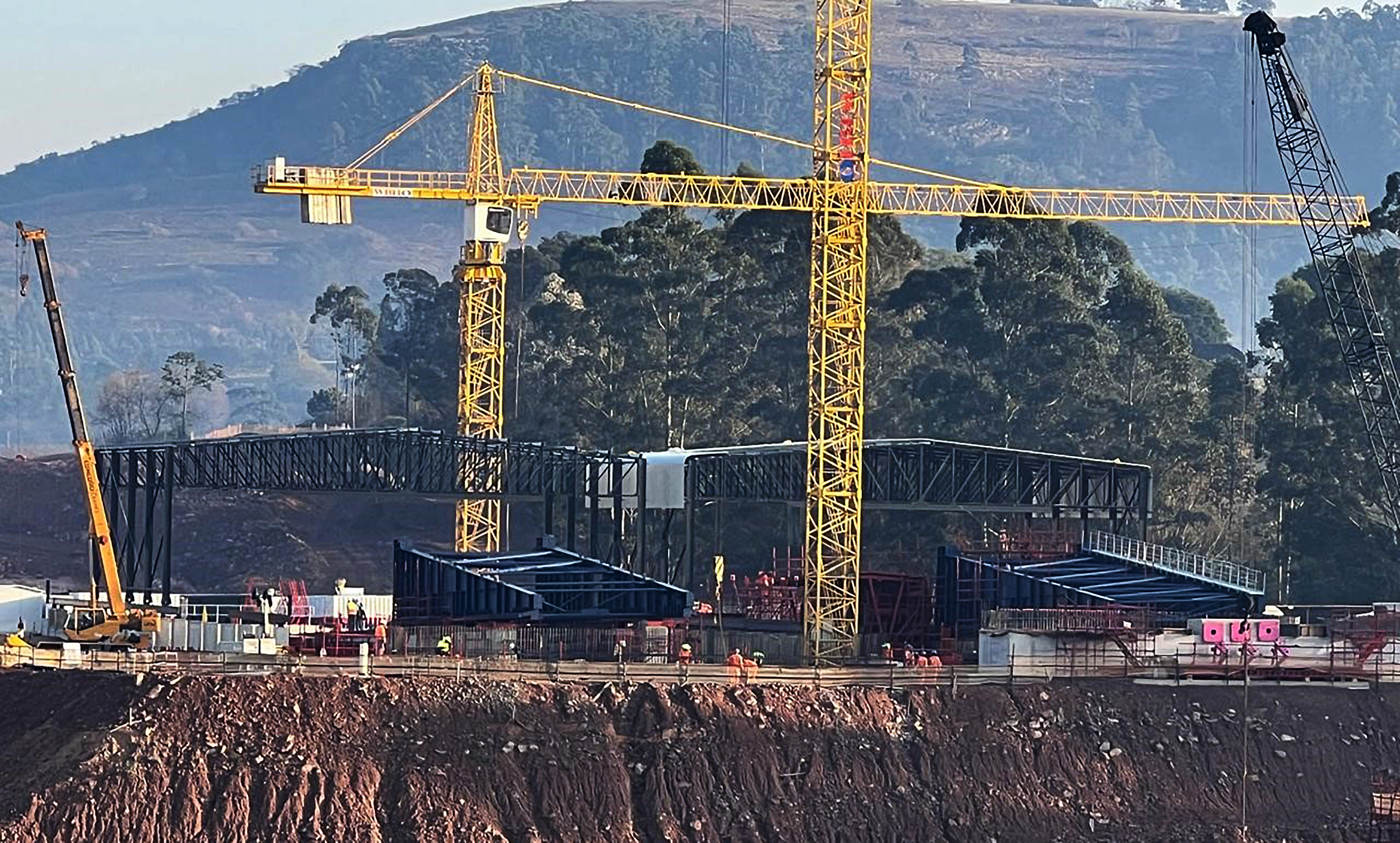
Key Ridge Viaducts, KZN: Two 362m incrementally launched, prestressed hollow box girder bridges. Enhancing vital national infrastructure.

Structural Details
The total length of the viaducts are 362m with the following span arrangement:
- Each bridge deck consist of 2x end spans of 33,8m between the abutments and the first pier adjacent to the abutments and 7 internal spans with a length of 42m each.
- Each bridge deck has a downhill slope of 3.5% from abutment A1 (South) to abutment A2 (North) as well as a slight horizontal curve and consists of 26 segments that are approximately 14m in length.
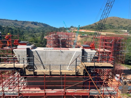
- The casting yards where segments are constructed are located behind Abutment A2 (North) and consist of two end to end casting bays constructed in concrete that are founded on bored piles due to poor geological conditions. The casting yard incorporates a stationary steel formwork system that provide the cross sectional shape of the deck segments.
- The bridge decks consist of a standard hollow box girder with 23m wide top slab at a 3,5% cross fall. The exceptionally wide top slab of the bridge deck is designed to accommodate 5x lanes of traffic with a 1,7m wide traffic shoulder and a concrete barrier each side, which required the addition of permanent steel struts to support the extended top slab cantilevers. This also required the construction of the top slab in two phases or casts, with the first being done in casting bay 1 after casting of the bottom slab and webs, and the second being the casting of the extended top slab section in casting bay 2 after the segment had been launched from casting bay 1 to casting bay 2. This requirement are the primary reason for the shorter than normal segments.
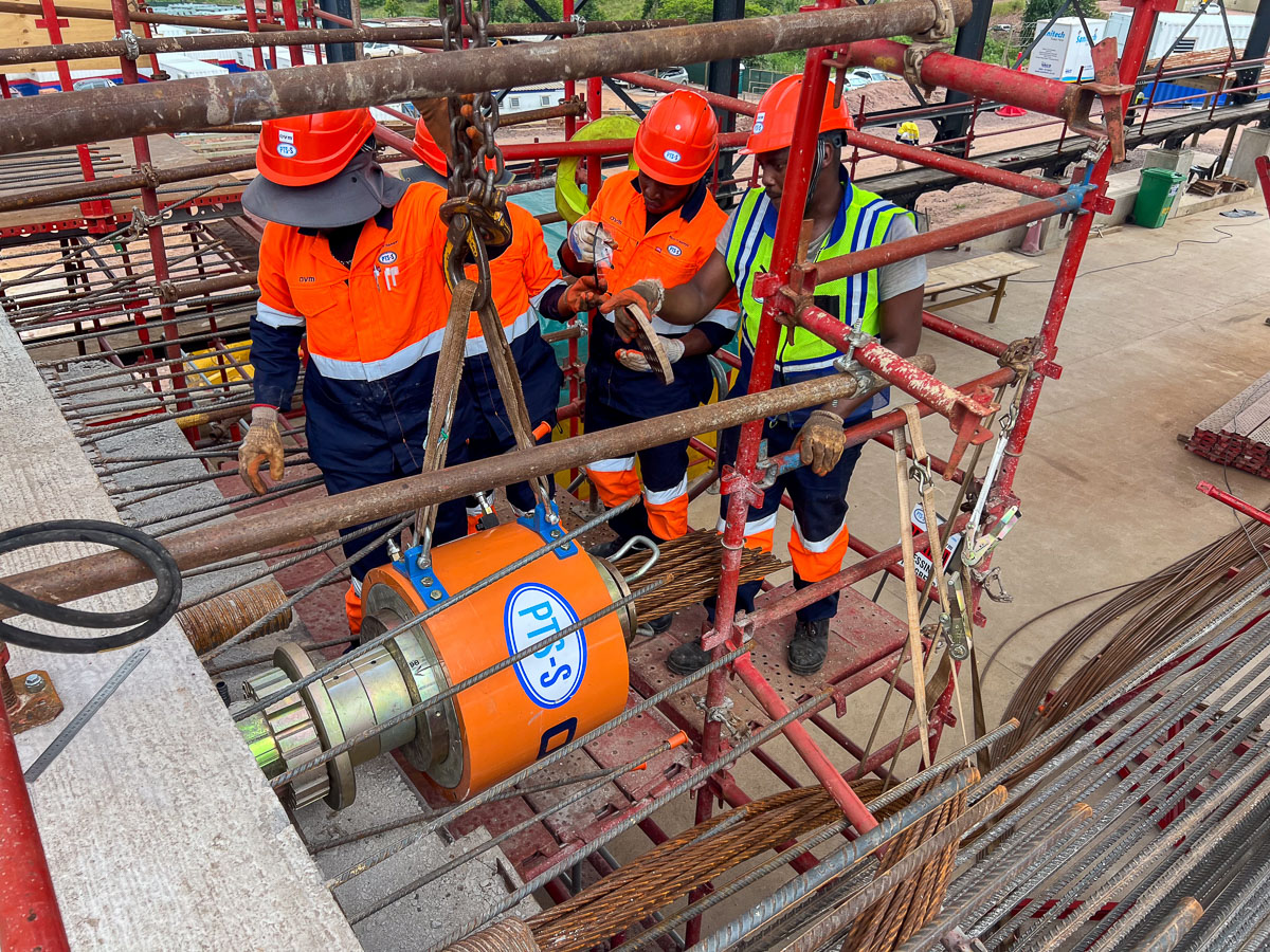
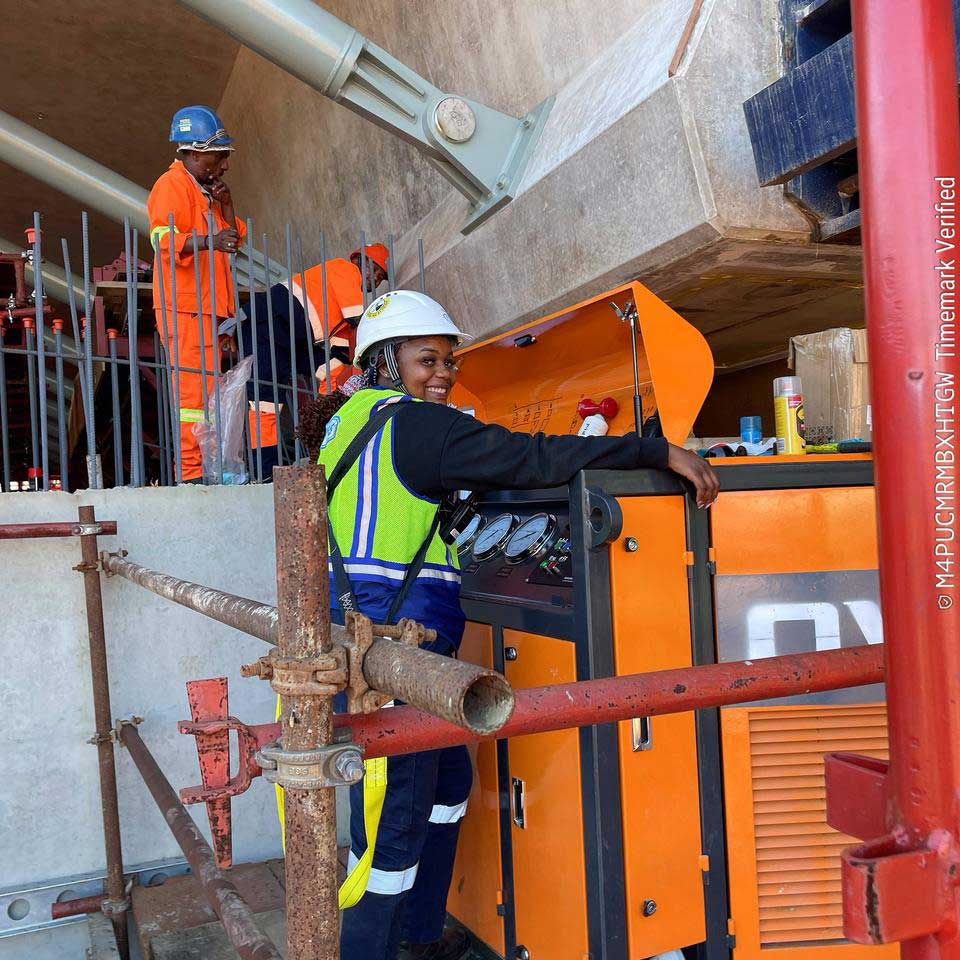
- The pulling method adopted for launching consists of hydraulic strand jacks with pull pins located in bridge deck. The wider than normal top slab resulted in a heavier than normal deck weight, which combined with the longitudinal 3,5% uphill launch slope, required the use of 3x 600t strand jacks for launching for the final stages of launching
Post-Tensioning & Structural Solutions (PTS-S) Scope
PTS-S were subcontracted by the main contractor, WBHO (Roads & Earthworks division) for the following specialist scope of work:
Post tensioning supply and execution, consisting of the following:
- Concentric Cable Tendons:
- Located in top and bottom slabs of the bridge deck in the longitudinal direction
- Tendons extend over 2x segments at a time for the full 362m length of the bridge deck and are joined in an alternating manner at every second joint between deck segments using coupling anchors
- These tendons provide an axial prestress force to the bridge deck to resist bending moments due to the deck self-weight as well as construction loads during the construction phase, and then after launching in combination with the draped cable tendons for the deck self-weight as well as traffic loads.
- Draped Cable Tendons:
- Located in webs of bridge deck
- Profiled to a parabolic profile within the webs, with low points at mid-span and high points at the supports, enhancing moment capacity of the bridge superstructure under permanent and traffic loads.
- Cables are installed on completion of launching process through preformed ducts that are cast into the webs during the construction phase, and stressed once the full superstructure is in it’s final position.
- Draped cable tendons supplements the concentric cable tendons by enhancing flexural performance of the bridge deck superstructure over multiple spans.
- Transverse Cable Tendons:
- Straight cable tendons that are located transversely in the bridge deck top slab of bridge deck perpendicular to the deck’s longitudinal axis
- Placed in the bridge deck top slab to enhance shear capacity, control transverse cracking and enhance the cantilever bending moment resistance of the top slab due to its excessive width.
- Enhances the distribution of stresses across the width of the bridge deck box girder, especially under traffic loading.
- Incremental launching services, which included the following:
- Casting yard design, including temporary piers & thrust beams between casting yard and abutments to transfer launch forces from the abutments where launching equipment were located, to the casting yard concrete structure and it’s piled foundation, which were specifically designed to resist the high thrust forces associated with the launching activities
- Design & installation of temporary pier stays to stabilize piers against the horizontal forces during launching as the bridge deck slides over the launch bearings on the piers
- Design, fabrication, supply and installation of launching girders
- Design, fabrication, supply and installation of movable cover over casting yard
- Design, fabrication, supply and installation of temporary launch bearings, including the supply of reinforced elastomeric sliding pads with PTFE layer on one side to facilitate the sliding of the bridge deck over the temporary launch bearings
- Design, fabrication, supply, installation and operation of bridge launching system, including hydraulic jacking equipment and any modifications to permanent works to accommodate the method of launching
- Design, supply and installation of electronic pier monitoring system to monitor pier deflections during launching operations
003-020-2017/7
South African National Roads Agency Limited
National Route 3, from Key Ridge to Hammarsdale Sterkspruit East Valley Viaducts.
Sterkspruit Valley East Viaducts (B0291 A & B), located on the N3 in the outer Durban area of Kwazulu Natal between Hillcrest and Hammarsdale
WBHO Roads & Earthworks
BVi Consulting Engineers
June 2024
Get Your Project Started Today
Ready to elevate your construction project? Contact us now for a tailored consultation or to receive a detailed quote for our specialised services.